Electric Fields in Physics: Key Concepts, Examples, and Calculation Methods
Understanding the Concept of Electric Field
The unit of the electric field is volts per meter (V/m) or newtons per coulomb (N/C).
Sources of Electric Fields
Electric fields are created by electric charges and varying magnetic fields. There are two primary sources:
- Point Charges: A single charged particle creates a radial electric field around it. The field's strength decreases with the square of the distance from the charge.
- Continuous Charge Distributions: Distributions of charges, such as charged plates or rods, produce electric fields that can be calculated by integrating the contributions from each infinitesimal charge element.
Visualizing Electric Fields
Electric fields are often visualized using electric field lines:
- Direction: Field lines point away from positive charges and towards negative charges.
- Density: The density of field lines represents the field's strength; closer lines indicate a stronger field.
- Behavior: Field lines never cross, and they always begin and end on charges or extend to infinity in the case of isolated charges.
Calculating Electric Fields
The electric field due to a point charge () at a distance () is given by Coulomb's law:
where is the permittivity of free space. For more complex charge distributions, the electric field is obtained by summing or integrating the contributions from all individual charges.
Applications of Electric Fields
Electric fields have a wide range of applications in both everyday life and advanced technology:
- Electronics: Understanding electric fields is essential for designing and analyzing electronic components like capacitors, transistors, and semiconductors.
- Medical Devices: Electric fields are used in medical imaging techniques such as MRI and in treatments like electrotherapy.
- Environmental Applications: Electric fields play a role in pollution control technologies, such as electrostatic precipitators used to clean industrial emissions
Electric Field Strength (E)
Definition: Electric field strength, often denoted by , is a vector quantity that represents the force per unit charge exerted on a positive test charge placed within the field. It indicates both the magnitude and direction of the force that a charge would experience.
Formula: The electric field strength is calculated using the formula:
where:
- is the electric field strength,
- is the force experienced by the test charge,
- is the magnitude of the test charge.
Units: The SI unit for electric field strength is volts per meter (V/m) or newtons per coulomb (N/C).
Characteristics:
- The direction of the electric field is the direction of the force that a positive test charge would experience.
- The field strength decreases with distance from the source charge.
- In a uniform electric field, the field strength remains constant throughout the region.
Electric Flux Density (D)
Definition: Electric flux density, symbolized by , also known as electric displacement field, quantifies the amount of electric flux passing through a given area. It is a measure of the distribution of the electric field in a material and relates the electric field to the electric charges present in the system.
Formula for Electric Flux Density
The electric flux density is defined as:
Where:
- is the electric flux density, measured in coulombs per square meter (C/m²).
- is the permittivity of the medium, measured in farads per meter (F/m). It is the product of the permittivity of free space () and the relative permittivity () of the material:
- : Permittivity of free space, approximately .
- : Relative permittivity (also called the dielectric constant) of the material.
- is the electric field intensity, measured in volts per meter (V/m).
Gauss's Law in Integral Form
The electric flux density is related to Gauss's Law, which states that the total electric flux through a closed surface is equal to the total charge enclosed by that surface:
Where:
- denotes the surface integral over the closed surface .
- is a differential area vector on the surface , pointing outward.
- is the total charge enclosed within the surface .
Relationship with Charge Density
The electric flux density is also related to the charge distribution within a material. In differential form, Gauss's Law states:
Where:
- is the divergence of the electric flux density.
- is the free charge density, measured in coulombs per cubic meter (C/m³).
Examples of Electric Flux Density Calculations
Let's look at a couple of examples to understand how to calculate electric flux density in different scenarios.
Example 1: Electric Flux Density in a Vacuum
Consider a point charge placed in a vacuum. The electric flux density at a distance from the charge is given by:
Where:
- is the radial unit vector pointing outward from the charge.
- The expression represents the electric flux density due to a point charge in a vacuum.
Example 2: Electric Flux Density in a Dielectric Medium
Consider a parallel plate capacitor with a dielectric material between the plates. Let:
- The charge density on the plates be .
- The relative permittivity of the dielectric be .
The electric flux density inside the dielectric is:
Where can be calculated using:
So, the electric flux density becomes:
Here, is the surface charge density, indicating that directly equals the charge density in the dielectric, showing that electric flux density accounts for both free and bound charges in the medium.
Electric Charge (Q)
Definition: Electric charge, denoted by , is a fundamental property of matter that causes it to experience a force in an electric field. Charges can be positive or negative, with like charges repelling and opposite charges attracting each other.
Q = CV
Units: The SI unit of electric charge is the coulomb (C).
Characteristics:
- The smallest unit of charge is the elementary charge, , approximately equal to coulombs.
- Charge is conserved, meaning it cannot be created or destroyed but only transferred.
- Charge can be quantized, appearing in discrete amounts (multiples of ).
Dielectric
Dielectric is the medium separating the plates of an insulator.
Permittivity of Free Space (𝜀₀)
Definition: Permittivity of free space, symbolized as , is a constant that describes how an electric field affects and is affected by a vacuum. It is a measure of the ability of a vacuum to permit electric field lines.
Value: (farads per meter)
Significance:
- It appears in Coulomb's law and other fundamental equations in electromagnetism, such as Gauss's law.
- It helps determine the capacitance of capacitors in a vacuum.
Relative Permittivity (εr)
Definition: Relative permittivity, also known as the dielectric constant and denoted by
Formula:
where:
- is the relative permittivity,
- is the permittivity of the material,
- is the permittivity of free space.
Characteristics:
- is greater than 1 for all materials, with for a vacuum.
- Materials with high are used as dielectrics in capacitors to increase capacitance.
- It is temperature-dependent and can vary with the frequency of the applied electric field.
Terminologies
1)
Capacitance is the measure of the ability to store electric charge.
2)
Charging is the process of increasing the charge held in a
capacitor
3)
Discharging is the process of reducing the charge held in a
capacitor.
Understanding Capacitors: Principles, Types, and Applications
Capacitors are fundamental components in electronic circuits, used to store and release electrical energy. Their unique ability to manage electrical charge makes them essential in various applications, from simple electronic devices to complex systems.
1. What is a Capacitor?
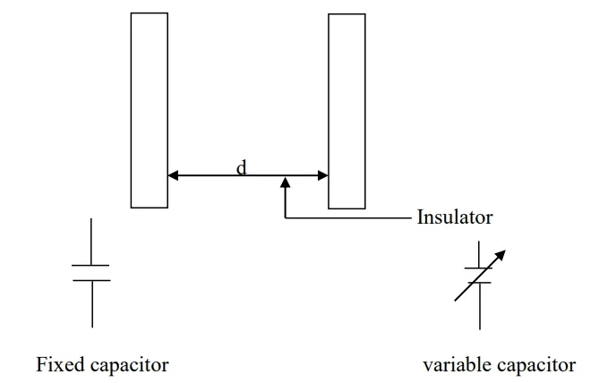
A capacitor is a passive electronic component that consists of two conductive plates separated by an insulating material called a dielectric. When a voltage is applied across the plates, an electric field develops, causing positive and negative charges to accumulate on the plates, thus storing energy. For more details, check out What is a Capacitor?.
2. How Do Capacitors Work?
Capacitors work based on the principle of electrostatics. When connected to a power source, they store energy in the electric field created between the plates. The amount of stored charge depends on the voltage applied and the capacitance of the capacitor:
- Capacitance () is the ability of a capacitor to store electrical charge. It is measured in farads (F) and is defined as the amount of electric charge stored per unit voltage across the capacitor's plates.
Where:
- = Capacitance (farads)
- = Electric charge (coulombs)
- = Voltage (volts)
3. Types of Capacitors
Capacitors come in various types, each with specific characteristics suited to different applications:
- Ceramic Capacitors: Made from ceramic materials, they are widely used for their low cost and high stability. They are commonly found in electronic circuits as filters or in timing applications. More on Ceramic Capacitors.
- Electrolytic capacitors: They consist of two aluminum foils, one with an oxide film/skin and one without. Electrolytic capacitors must be connected to the correct voltage polarity to prevent damage to the oxide film/skin. The main disadvantages of this type of capacitor are (a) the insulation resistance is comparatively low (b) it is only suitable for circuits where the voltage applied to the capacitor never reverses its direction. They are used where a large capacitance is required and where the terminal voltage never reverses polarity. Learn about Electrolytic Capacitors.
- Tantalum Capacitors: Similar to electrolytic capacitors but with better performance in terms of stability and leakage current. They are used in applications where space and reliability are crucial.
- Film Capacitors: Made from thin plastic films, these capacitors are known for their excellent stability and low loss. They are used in precision applications like audio equipment and signal processing.
- Supercapacitors: Also known as ultracapacitors, they have very high capacitance values and are used for energy storage, providing quick bursts of energy. Understanding Supercapacitors.
- Paper capacitors: They consist of thin aluminum foils separated by a layer of waxed paper. Paper capacitors are used in household appliances (e.g. fluorescent lighting fittings) and power circuits (e.g. motors).
- Mica capacitors: They are constructed of thin aluminum foils separated by a layer of mica. With low dielectric loss. The main disadvantage of this type of capacitor is that it is relatively expensive. They are often used in high-frequency electronic circuits.
- Air capacitors: They are usually constructed of multiple aluminum vanes of which one section moves to make the capacitance variable. They are often used for radio tuning circuits.
- Polyester capacitors: They are manufactured in a very thin film of thickness as little as 2μm and metallized on one side. They can operate at high voltage.
4. Applications of Capacitors
Capacitors have a wide range of applications in electronics and electrical systems:
- Energy Storage: Supercapacitors store energy and deliver it quickly, useful in backup power systems and regenerative braking in electric vehicles. Energy Storage Capacitors.
- Filtering: Capacitors filter out noise from power supplies and signals, crucial in audio equipment and communication systems. Capacitors in Filtering Applications.
- Timing and Oscillation: Capacitors, in combination with resistors and inductors, create timing circuits and oscillators, which are essential in clocks, radios, and signal processing. Timing Circuits and Oscillators.
- Coupling and Decoupling: Capacitors block DC signals while allowing AC signals to pass, which is useful in separating different parts of circuits and stabilizing voltage levels.
- Tuning Circuits: In radio and television receivers, capacitors help tune circuits to select specific frequencies. Tuning Circuits with Capacitors.
5. Key Characteristics and Considerations
When selecting a capacitor for a specific application, several key characteristics must be considered:
- Capacitance Value: Determined by the physical properties of the capacitor, including the area of the plates, the distance between them, and the dielectric material. Capacitance Basics.
- Voltage Rating: The maximum voltage a capacitor can handle without breaking down. Exceeding this voltage can lead to capacitor failure. Voltage Rating in Capacitors.
- Equivalent Series Resistance (ESR): Represents the resistance within the capacitor, which can affect its performance, especially in high-frequency applications. Understanding ESR in Capacitors.
- Temperature Coefficient: Indicates how the capacitance value changes with temperature, crucial for applications requiring stability under varying environmental conditions. Temperature Coefficient in Capacitors.
Parallel-Plate Capacitors: Structure, Function, and Applications
A parallel-plate capacitor is a type of capacitor where two conductive plates are placed parallel to each other with a dielectric material in between. This arrangement allows the capacitor to store electrical energy in the form of an electric field between the plates.
Structure and Working Principle:
Conductive Plates: The plates, usually made of a metal like aluminum or copper, act as the electrodes. When a voltage is applied across these plates, an electric field is established, and charges of opposite polarity accumulate on the plates.
Dielectric Material: The dielectric is an insulating material placed between the plates. It increases the capacitor's capacitance by reducing the electric field's strength for a given charge on the plates. Common dielectric materials include air, glass, ceramic, plastic, or mica.
Electric Field and Charge Storage: The electric field created between the plates stores energy. The amount of charge () stored is proportional to the applied voltage () and the capacitance () of the capacitor:
Capacitance Calculation: The capacitance of a parallel-plate capacitor is determined by the formula: Where:
- is the permittivity of the dielectric material (product of the permittivity of free space, , and the relative permittivity, )
- is the area of one of the plates
- is the separation distance between the plates
Key Factors Affecting Capacitance:
- Area of the Plates (): A larger plate area results in a higher capacitance, as there is more surface area to store charge.
- Distance Between Plates (): Reducing the distance between the plates increases the capacitance, as the electric field strength is higher for a given charge.
- Dielectric Material (): The type of dielectric material affects the capacitance. Materials with a higher relative permittivity () increase the capacitance by allowing more charge to be stored for a given voltage.
Applications of Parallel-Plate Capacitors:
- Energy Storage: Used in electronic circuits to store energy, smooth out fluctuations, and provide power during short interruptions.
- Filtering: In power supplies, parallel-plate capacitors filter out unwanted noise and stabilize voltage.
- Timing Circuits: In conjunction with resistors, these capacitors are used in RC timing circuits for generating time delays or oscillations.
- Sensors: Parallel-plate capacitors can act as sensors, measuring changes in physical quantities like distance, pressure, or humidity by detecting changes in capacitance.
Energy stored in a capacitor
W = ½ CV2
Multi-Plate Capacitors: Enhancing Capacitance in Compact Spaces
Definition:
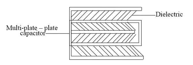
A multi-plate capacitor, also known as a multi-layer capacitor, consists of more than two conductive plates separated by dielectric layers. This design increases the overall capacitance without significantly increasing the physical size of the capacitor, making it ideal for applications that require high capacitance in a compact form.
Structure and Working Principle:
Multiple Conductive Plates:
Multi-plate capacitors have alternating layers of conductive plates and dielectric material. The plates are typically made from metals like aluminum or copper.Dielectric Layers:
The dielectric layers separate each conductive plate from the next. Materials such as ceramic, mica, or plastic are commonly used, depending on the desired properties like permittivity and breakdown voltage. For more information on dielectric materials, visit this page.Capacitance Enhancement:
The total capacitance () of a multi-plate capacitor is the sum of the capacitance between all the individual pairs of plates. For 𝑛 plates, there are 𝑛−1 gaps, and the total capacitance is given by:
Where:
- = Number of plates
- = Area of each plate
- = Distance between adjacent plates
- = Permittivity of the dielectric material, given by
- = Permittivity of free space ()
- = Relative permittivity of the dielectric material
The formula for calculating total capacitance can be found here.
Connection Configuration:
Typically, alternating plates are connected in parallel. This connection increases the effective capacitance for the same plate area and dielectric thickness. For a deeper understanding of capacitor connections, check out this article.
Advantages of Multi-Plate Capacitors:
High Capacitance in Small Size:
Multi-plate capacitors achieve higher capacitance values than simple parallel-plate capacitors of similar size. For details on high-capacitance capacitors, see this resource.Efficient Use of Space:
Their compact design makes them ideal for space-constrained applications like smartphones and laptops. Learn about space-saving capacitor designs here.Enhanced Performance:
Multi-plate capacitors offer lower equivalent series resistance (ESR) and higher stability.
Applications:
Decoupling and Filtering:
Multi-plate capacitors are widely used in electronic circuits for decoupling and filtering noise.Energy Storage:
They are effective in applications requiring quick energy storage and discharge, such as camera flashes and RF circuits. Read more about energy storage applications here.Precision Circuits:
Due to their stable capacitance values, they are used in precision circuits like oscillators and signal processing equipment.
Numerical Examples
1) A parallel plate capacitor consists of 5 metal plates
each of area 40cm2 separated by a dielectric of thickness 0.25mm,
whose relative permittivity is 5. Calculate the capacitance of the capacitor [𝜀𝑜 = 8.85 x 10⁻¹²F/m]
Solution
2) A capacitor is made with 7metal and separated by
sheets of mica having a thickness of 0.3mm and a relative permittivity of 6.
The area of one side of each plate is 500cm2 and a Pd of 400V is
maintained across its terminals. Calculate
a.
The capacitance in micro farads
b.
The charge
c.
The potential gradient
d.
The energy stored
[𝜀𝑜 = 8.85x10⁻¹²F/m]
3) A capacitor has seven parallel plates separated by
sheets of mica, 0.5mm thick and a relative permittivity of 6. The capacitor
whose area of each plate is 500cm2 is connected to a 400V supply.
Calculate the
a.
Electric field strength
b.
Capacitance of the capacitor
c.
Electric flux density.
[eo =8.85x10⁻¹²F/m]
Type of Capacitor Connections
Capacitors can be connected in various ways to achieve different total capacitance and voltage ratings. The two most common types of capacitor connections are series and parallel. Each type affects the overall capacitance, voltage handling, and energy storage capabilities of the circuit.
1. Series Connection
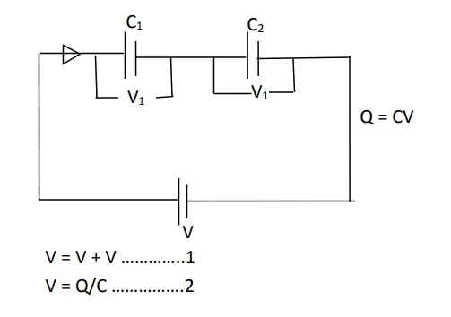
In a series connection, capacitors are connected end-to-end, so the charge on each capacitor is the same. The total capacitance of capacitors in series is given by the reciprocal of the sum of the reciprocals of the individual capacitances:
If V1 and V2 are the corresponding p.ds across C1 and C2 respectively
Q = C1V1 Q = C2V2
V1 = Q/C1 V2 = Q/C2
But Q = CV or V = Q/C
V = V1 + V2
V1 + V2 = 𝑄/𝐶
𝑄/𝐶 = V1 + V2
𝑄/𝐶 = 𝑄/𝐶1 + 𝑄/𝐶2
Q (1/𝐶) = Q(1/𝐶1 + 1/𝐶2 )
Dividing through by Q
Numerical Example
1) If two capacitors having capacitance of 6µF and 12µF respectively are connected in series across a 200V supply, find the
a. Total capacitance of the capacitor
b. The pd (voltage) across each capacitor
c. The charge on each capacitor
Solution
When capacitors are connected in series, the total capacitance can be calculated using the formula:
where and .
a. Total Capacitance of the Capacitors
So, the total capacitance of the capacitors in series is 4 µF.
b. Potential Difference (Voltage) Across Each Capacitor
The total voltage is divided between the capacitors in series inversely proportional to their capacitance. The voltage across each capacitor and can be found using:
Since the charge is the same on each capacitor, and we know:
Using the formula:
Now, we can find and :
Therefore, the potential difference across each capacitor is:
- 6 µF capacitor: 133.33 V
- 12 µF capacitor: 66.67 V
c. Charge on Each Capacitor
In a series circuit, the charge on each capacitor is the same and equal to the total charge:
Therefore, the charge on each capacitor is 800 µC.
Summary
- Total Capacitance: 4 µF
- Voltage across 6 µF Capacitor: 133.33 V
- Voltage across 12 µF Capacitor: 66.67 V
- Charge on Each Capacitor: 800 µC
Note
In series connection
V1 = 𝑄/𝐶1= V2 = 𝑄/𝐶2
- Total Capacitance: The total capacitance is always less than the smallest individual capacitor.
- Voltage: The total voltage across the series is the sum of the voltages across each capacitor.
- Charge: All capacitors in series have the same charge.
Series connections are useful for increasing the voltage rating of the combined capacitors without changing the capacitance significantly.
2. Parallel Connection
In a parallel connection, all capacitors are connected with their positive terminals together and their negative terminals together. The total capacitance is the sum of the individual capacitances:
- Total Capacitance: The total capacitance is the sum of all the individual capacitances.
- Voltage: The voltage across each capacitor is the same as the total voltage across the combination.
- Charge: The total charge stored is the sum of the charges stored on each capacitor.
Parallel connections are useful for increasing the total capacitance without changing the voltage rating.
Let's go through each part of the problem:
a) Total Capacitance of the Capacitors
For capacitors in parallel, the total capacitance is given by:
where:
Plug these values into the formula:
Total Capacitance: 14 µF
b) Charge on Each Capacitor
The charge on each capacitor in parallel is given by:
where is the supply voltage. Let's calculate the charge on each capacitor:
- Charge on the 2 µF Capacitor ():
- Charge on the 4 µF Capacitor ():
- Charge on the 8 µF Capacitor ():
Charge on Each Capacitor:
- 2 µF Capacitor: 80 µC
- 4 µF Capacitor: 160 µC
- 8 µF Capacitor: 320 µC
c) Total Energy Stored
The total energy stored in capacitors in parallel can be calculated using the formula for the energy stored in a capacitor:
Here, is the total capacitance in parallel, which we found to be 14 µF, and is the supply voltage (40 V):
Total Energy Stored: 11.2 mJ
Summary
- Total Capacitance: 14 µF
- Charge on 2 µF Capacitor: 80 µC
- Charge on 4 µF Capacitor: 160 µC
- Charge on 8 µF Capacitor: 320 µC
- Total Energy Stored: 11.2 mJ
Trial Test
1.
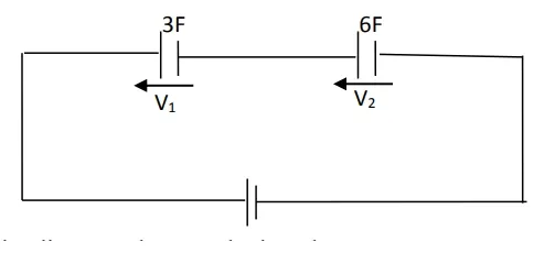
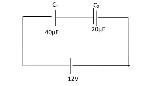
a. The diagram above is an arrangement of capacitors in a circuit. Calculate the
(a) Equivalent capacitance of the two capacitors in series
(b) Effective capacitance in the
(c) Charge on the 40µF
(d) Capacitor in the
(e) Voltage across C2.
b. Show that the total capacitance of two capacitors having capacitances C1 and C2 connected in series is C1C2/(C1+C2)
c. What factors affect the capacitance that exists between two plates insulated from each other
d. A capacitor consists of two metal plates, each having an area of 900cm2, spaced 3.0mm apart. The whole of the space between the plates is filled with a dielectric having a relative permittivity of 6.A p.d. of 500V is maintained between the two plates. Calculate the (a) capacitance
(b) charge
(c) electric field strength
(d) electric flux density
e. What are the factors which determine the capacitance of a parallel-plate capacitor?
3. Series-Parallel Combination
In practical circuits, capacitors are often arranged in combinations of series and parallel connections to achieve desired capacitance and voltage characteristics. For example, capacitors may be arranged in series to increase voltage tolerance, and these series combinations can be connected in parallel to increase total capacitance.
Applications of Capacitor Connections
- Series Connections: Used in power supply filtering, voltage multipliers, and tuning circuits.
- Parallel Connections: Common in power supply smoothing, energy storage, and bypassing applications.
Related Topics on Applied Electricity
- Emission of Electrons and Thermionic Devices
- Data Communication
- Digital Electronics
- Magnetic Field
- Electromagnetism
- Electric Field
- Direct Current Circuit Theory
- Applied Electricity Concise Notes for Senior High Schools (SHS 1, 2 & SHS 3)
- Careers in Applied Electricity
- Common Electrical Devices and Their Uses
- The Impact of Applied Electricity on Modern Technology


