Magnetic Field: Understanding Its Principles, Formulas, and Applications
Magnet
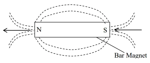
A magnet is a material (substance) that attracts a magnetic material. They come in various shapes and sizes, including bar magnets, horseshoe magnets, and disc magnets. The ability of a magnet to attract and repel is due to the alignment of microscopic magnetic domains within the material. The relationship between magnetism and electricity has led to the invention of appliances such as radio set, television set, loud speakers, transformers, electric motors, microphone, etc.
.
Types of Magnets
- Permanent Magnets: These retain their magnetic properties over time. Examples include neodymium magnets and ceramic magnets.
- Temporary Magnets: These act like permanent magnets when in a strong magnetic field but lose their magnetism when the field is removed.
- Electromagnets: Created by passing electric current through a coil of wire, electromagnets are used in devices like motors and generators.
Magnetic Circuit
Magnetic circuits are a foundational concept in electromagnetism, playing a crucial role in designing devices like transformers, inductors, and electric motors. Understanding magnetic circuits is essential for electrical engineers and physicists as they provide insight into how magnetic fields interact with materials to perform work or transfer energy.
This article will delve into the essential principles of magnetic circuits, explore the analogy with electrical circuits, provide key formulas, and solve typical problems that illustrate these concepts.
What is a Magnetic Circuit?
A magnetic circuit is a closed path or loop through which magnetic flux flows. It consists of magnetic materials and air gaps designed to guide magnetic lines of force (flux) to specific areas. Just like an electrical circuit, a magnetic circuit can be analyzed and calculated using similar laws and concepts.
Components of a Magnetic Circuit
Magnetic Core: A material with high magnetic permeability, such as iron or ferrite, that confines and directs magnetic flux.
Magnetic Flux (): The total magnetic field passing through a given area, measured in Weber (Wb).
Magnetic Flux Density (): The concentration of magnetic flux in a given area, measured in Tesla (T). It is defined as the flux per unit area.
Magnetomotive Force (MMF): The force that drives magnetic flux through a magnetic circuit, analogous to electromotive force in an electrical circuit. It is measured in Ampere-Turns (At).
Reluctance (): The opposition that a material presents to magnetic flux, similar to resistance in an electrical circuit.
Permeability (): A measure of how easily a material allows magnetic flux to pass through it, measured in Henry per meter (H/m).
Air Gap: A non-magnetic section of a magnetic circuit that introduces additional reluctance and is used to control the flux.
Magnetic Field Strength (): The intensity of the magnetic field applied to a material, influencing how much magnetic flux is produced in the circuit. Measured in Ampere per meter (A/m).
Analogies with Electrical Circuits
Magnetic circuits bear a striking resemblance to electrical circuits. Here are the parallels:
|
Electrical Circuit |
Magnetic Circuit |
|
Current () |
Magnetic Flux () |
|
Voltage () |
Magnetomotive Force (MMF) |
|
Resistance () |
Reluctance () |
|
Conductance () |
Permeance () |
|
Ohm's Law () |
Hopkinson's Law () |
Key Formulas in Magnetic Circuits
Understanding the following key formulas is crucial for analyzing and solving problems related to magnetic circuits:
1. Magnetomotive Force (MMF)
The magnetomotive force (MMF) is the magnetic analog of electromotive force (EMF) and is given by:
where:
- = Number of turns in the coil,
- = Current through the coil (A).
2. Magnetic Flux ()
The total magnetic field passing through a surface area is calculated as:
where:
- = Magnetic flux density (T),
- = Area through which flux passes (m²).
3. Reluctance ()
Reluctance is analogous to electrical resistance and is given by:
where:
- = Length of the magnetic path (m),
- = Permeability of the material (H/m),
- = Cross-sectional area of the magnetic path (m²).
4. Ohm's Law for Magnetic Circuits (Hopkinson's Law)
Just like Ohm's Law for electrical circuits, Hopkinson's Law relates MMF, flux, and reluctance:
5. Permeance ()
Permeance is the reciprocal of reluctance, representing the ease with which flux passes through a material:
6. Magnetic Field Strength ()
Magnetic Field Strength () plays a significant role in characterizing the magnetic properties of a material. It's particularly useful for understanding how a material reacts to a magnetic field. Here’s a deeper look:
- Definition: measures the intensity of a magnetic field at any point within the circuit.
Calculation: Determined by the formula:
- Applications: Used in designing magnetic circuits to ensure that the material operates below its saturation point.
Example: For a solenoid with 300 turns carrying a current of 1.5 A over a length of 0.3 m:
The magnetic field strength is
Calculations
Problem 1: Calculating Magnetic Flux in a Core
A magnetic core has a cross-sectional area of and is subject to a magnetic flux density of
Solution:
Use the formula for magnetic flux:
where:
Plug in the values:
The magnetic flux through the core is
Problem 2: Calculating Reluctance of a Magnetic Path
Calculate the reluctance of a magnetic path with a length of , and a material permeability of .
Solution:
Use the formula for reluctance:
where:
- ,
- .
Calculate :
Now calculate the reluctance:
The reluctance of the magnetic path is approximately .
Problem 3: Calculating MMF for a Magnetic Circuit
Determine the magnetomotive force required to produce a magnetic flux of through a magnetic circuit with a total reluctance of .
Solution:
Use Hopkinson's Law:
where:
- ,
- .
Plug in the values:
The magnetomotive force required is .
Problem 4: Calculating Magnetic Field Strength ()
A solenoid with 600 turns and a length of carries a current of . Calculate the magnetic field strength inside the solenoid.
Solution:
Use the formula for magnetic field strength:
where:
- ,
- ,
- .
Plug in the values:
The magnetic field strength inside the solenoid is .
Problem 5: An iron ring of mean circumference 100cm and of uniform cross –sectional area 5cm2 has a coil consisting of 500 turns. The current through the coil is 5A and the relative permeability of iron is 450.
Calculate
(a) The magnetizing force
(b) The flux density
(c) The total flux
Solution
To solve this problem, we need to apply the principles of magnetic circuits, specifically focusing on calculating the magnetizing force, flux density, and total flux for an iron ring with given parameters.
Here are the calculations for each part:
Given Data:
- Mean circumference of the iron ring (): 100 cm = 1 m
- Cross-sectional area (): 5 cm = m
- Number of turns (): 500
- Current (): 5 A
- Relative permeability (): 450
- Permeability of free space (): H/m
(a) Calculating the Magnetizing Force ()
The magnetizing force, also known as the magnetic field strength (), is determined using the formula:
Where:
- is the number of turns of the coil.
- is the current through the coil in amperes (A).
- is the mean length of the magnetic path in meters (m).
Step-by-Step Calculation:
- Number of turns (): 500 turns
- Current (): 5 A
- Mean circumference (): 1 m
Substitute the given values into the formula:
Therefore, the magnetizing force () is 2500 A/m.
(b) Calculating the Flux Density ()
The flux density () is the amount of magnetic flux per unit area, and it is given by:
The absolute permeability () is calculated as:
Now, calculate :
So, the flux density () is approximately .
(c) Calculating the Total Flux ()
The total magnetic flux () is the product of the flux density and the cross-sectional area:
where:
- = Cross-sectional area (m).
Plug in the values:
So, the total flux () is approximately
Summary
Here's a summary of the calculations:
- Magnetizing Force ():
- Flux Density ():
- Total Flux (): .
Problem 6: A magnetic circuit has a cross – sectional area of 6 x 10⁻⁴m2 and mean length of 0.3m. A 40 – turn coil is rounded uniformly round the core. When a current of 1.5A passes in the coil, flux density of 0.5T was established in the circuit.
Calculate;
(a) The magnetic field strength
(b) The relative permeability of the magnetic material
Solution
To solve this problem, we need to calculate the magnetic field strength and the relative permeability of the magnetic material given the parameters of a magnetic circuit.
Given Data:
- Cross-sectional area ():
- Mean length of the magnetic path ():
- Number of turns (): 40
- Current ():
- Flux density ():
(a) Calculating the Magnetic Field Strength ()
The magnetic field strength can be calculated using the formula:
where:
- = Number of turns,
- = Current in the coil (A),
- = Mean length of the magnetic path (m).
Substitute the given values:
Thus, the magnetic field strength () is 200 A/m.
(b) Calculating the Relative Permeability
The relative permeability is given by the ratio of the absolute permeability to the permeability of free space . The formula for the absolute permeability is:
Where:
- = Flux density (T),
- = Magnetic field strength (A/m).
Calculate :
The permeability of free space is given as:
Now, calculate the relative permeability:
Thus, the relative permeability () is approximately 1988.46.
Summary
Here are the results of the calculations:
- Magnetic Field Strength ():
- Relative Permeability ():
Applications of Magnetic Circuits
Magnetic circuits are integral to various technological applications:
Transformers: Use magnetic circuits to transfer electrical energy between two or more circuits through electromagnetic induction.
Motors and Generators: Utilize magnetic circuits to convert electrical energy into mechanical energy (and vice versa).
Magnetic Relays: Employ magnetic circuits to open or close electrical contacts in response to changes in magnetic field strength.
Inductors: Store energy in the form of a magnetic field when current passes through them.
Electromagnets: Use a magnetic circuit to generate a controlled magnetic field.
Magnetization Curve of Ferromagnetic Materials
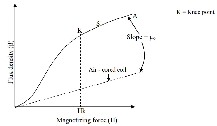
In an air – care coil, increasing the magnetizing force has the effect causing the flux density in the core to increase linearly form zero.
Magnetizing curve
When a ferromagnetic core is inserted in to the coil, a magnetizing curve (OA) is formed. Magnetic domains is the spinning motion of electrons in ferromagnetic material that produces tiny permanent magnetic effect between points 0 and k the flux density increases very rapidly because the application of a magnet field to the material causes the magnetic domains to align with the magnetic fluid. When the values of magnetizing force exceed. Hk, the rate increases of flux density diminishes because loss magnetic domains remain to be lined up.
Beyond the point marked, the curve is parallel to the line for the air – core coil because all the magnetic domains point in the direction of the applied field.
A material is said to be magnetically saturated when all the magnetic domain point in the directions of the applied field.
HYSTERESIS LOOP
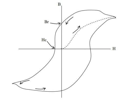
Hysteresis loop is a graphical representation use to describe how flux density varies with magnetic field strength in ferromagnetic material.
To plot a complete curve of how B varies with H, it is necessary to demagnetize the ferromagnetic material in a closed ring.
Demagnetization is achieved by gradually reducing the current through the magnetizing coil from a high value to zero and reversing the direction of the current repeatedly. E.g. of picture tube of a color TV set demagnetized when switched on. When the magnetizing force is reduced to zero, not all of the magnet domains material retains some magnetism called Remnant flux density.
Remanent Flux Density (Br)
It is the flux density remaining in the iron when reducing the magnetizing force to zero.
If the magnetizing force is increased in the reverse direction, the flux density gradually reduces to zero.
Coersive Fore (Hc)
It is a reversed magnetizing force used to reduce (wipe out) the residual (remanent) flux density.
Trial Test
A magnetize circuit consist of three parts X, Y and Z in series each with a uniform cross – section area.
Part length (cm) Area (cm2)
X 35 4.5
Y 10 3.0
Z 0.1 3.5
Part Z in air gap. Neglecting magnetic leakage and fringing, determine the number of ampere turn necessary on a coil which is uniformly wound on the magnetic circuit and produces a flux of 0.35mWb in the air gap, if the magnetic field strength of X is 490A/M and Y in 1360A/M Solution
Solution
To determine the number of ampere-turns necessary for the given magnetic circuit consisting of parts X, Y, and Z, we'll follow the principles of magnetic circuits, applying the concept of magnetic reluctance and magnetic field strength.
Given Data
- Magnetic Flux ():
Part X:
- Length (): 35 cm = 0.35 m
- Area (): 4.5 cm =
- Magnetic Field Strength (): 490 A/m
- Part Y:
- Length (): 10 cm = 0.10 m
- Area (): 3.0 cm =
- Magnetic Field Strength (): 1360 A/m
- Part Z (Air Gap):
- Length (): 0.1 cm = 0.001 m
- Area (): 3.5 cm =
- Permeability of Free Space ():
Approach
We'll calculate the number of ampere-turns required by computing the magnetomotive force (MMF) needed for each part of the magnetic circuit and then summing them up. The total MMF is the sum of the MMFs for parts X, Y, and the air gap Z.
Step 1: Calculating MMF for Part X
The magnetomotive force for part X is given by:
Step 2: Calculating MMF for Part Y
The magnetomotive force for part Y is given by:
Step 3: Calculating MMF for Air Gap (Part Z)
For the air gap, we first need to calculate the magnetic field strength in the air gap using the formula:
Where:
- is the flux density, which can be calculated as:
Now, calculate the magnetic field strength in the air gap:
Now, calculate the MMF for the air gap:
Step 4: Total MMF Required
The total MMF required is the sum of the MMFs for parts X, Y, and Z:
Step 5: Calculating the Number of Ampere-Turns
The number of ampere-turns () required is equal to the total MMF:
Thus, the number of ampere-turns necessary for the coil to produce the required flux is approximately 1103.27 turns.
Trial Test
(1) A coil of 500 turns is wounded on an iron ring. The ring has a mean cross – sectional area of 5cm2. If the total flux in the ring is 1.5 × 10⁻³wb and the relative permeability of the ring is 45.
Calculate;
(a) The flux density
(b) The magnetizing
(c)The reluctance of the circuit
(2) A mild steel ring has a mean circumference of 500mm and a uniform cross-sectional area of 300mm2. Calculate the mmf required to produce a flux of 500μWb.
Practical Applications of Magnets and Magnetic Fields
Magnets and magnetic fields are not just theoretical constructs; they are vital in various technological applications:
- Electric Motors: Use magnetic fields to convert electrical energy into mechanical energy.
- Generators: Convert mechanical energy into electrical energy using magnetic induction.
- Transformers: Utilize magnetic fields to transfer electrical energy between circuits.
- Magnetic Resonance Imaging (MRI): Employ strong magnetic fields to produce detailed images of the inside of the body.
- Magnetic Levitation: Used in maglev trains for frictionless movement.
Conclusion
Understanding magnets and magnetic fields is essential for anyone interested in physics or engineering. By mastering the formulas and concepts discussed here, you'll be well-equipped to tackle more complex problems and applications in this fascinating field.
Additional Resources
For further reading and exploration, consider visiting these reputable sources:
Related Topics on Applied Electricity
- Emission of Electrons and Thermionic Devices
- Data Communication
- Digital Electronics
- Magnetic Field
- Electromagnetism
- Electric Field
- Direct Current Circuit Theory
- Applied Electricity Concise Notes for Senior High Schools (SHS 1, 2 & SHS 3)
- Careers in Applied Electricity
- Common Electrical Devices and Their Uses
- The Impact of Applied Electricity on Modern Technology


